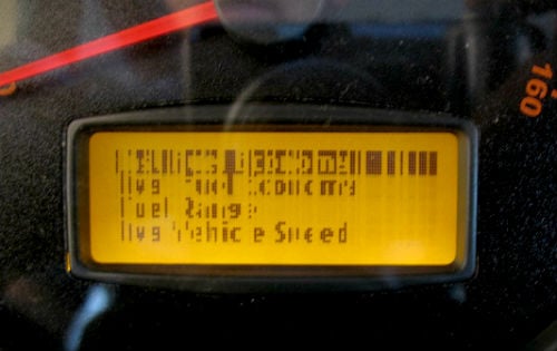
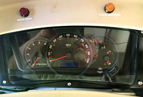
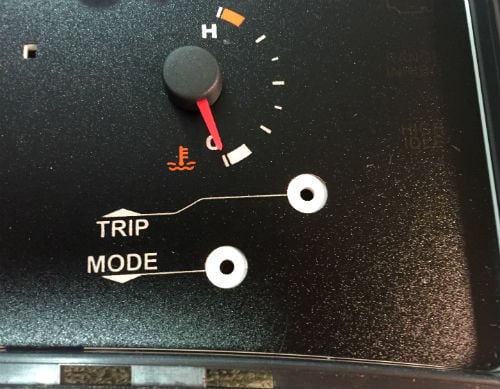
Over the several years of ownership, many Workhorse RV owners have experienced the disappointment of pixel drop-out on the Instrument panel mounted LCD.
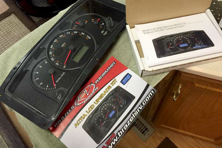
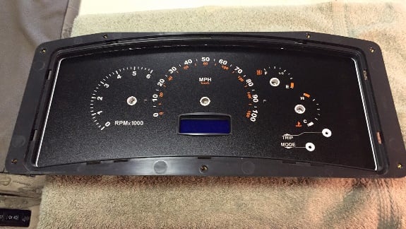
The Actia Instrument Cluster LCD Upgrade Kit from Ultra RV Products of Centralia, WA. Photos by Mike Pelchat
 For this article, we installed the new upgrade kit on a 2003 Winnebago Adventurer, as we found the system can be installed by most competent shade-tree mechanics. What attracted our attention to the upgraded system is it displays bright white text on a blue background, making it highly visible under most any lighting conditions. What`s also interesting is depending on your motorhome (and there are dozens), the IP can be mounted into the dash pod in several ways.
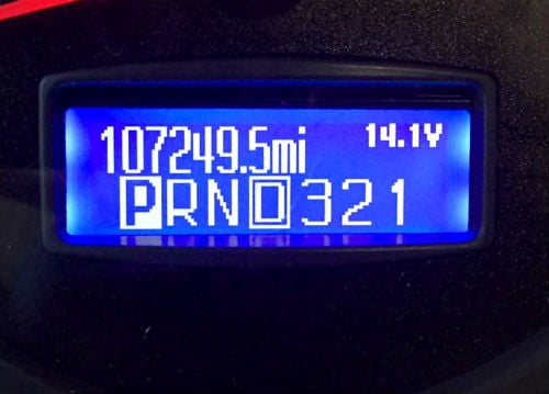
Top photo: The LCD with the pixel drop-out; bottom photo: the new LCD screen from Ultra RV Products.
Although the problem doesn’t affect the operation of the motorhome, it does make it nearly impossible to see the data that is presented on the vehicle’s command center.
Ultra RV Products of Centralia, WA, now offers the Actia Instrument Cluster LCD Upgrade Kit, which replaces the previous instrument system and LCD screen. It was commonly included in Class A motorhomes built on the Workhorse Chassis between 2003 to 2010.
You Can Install the LCD Upgrade Kit
For this article, we installed the new upgrade kit on a 2003 Winnebago Adventurer. The system can be https://rvlife.com/wp-admin/post.php?post=33844&action=editinstalled by most competent shade-tree mechanics. What attracted our attention to the upgraded system is it displays bright white text on a blue background, making it highly visible under most lighting conditions. What`s also interesting is depending on your motorhome (and there are dozens), the IP can be mounted into the dash pod in several ways.
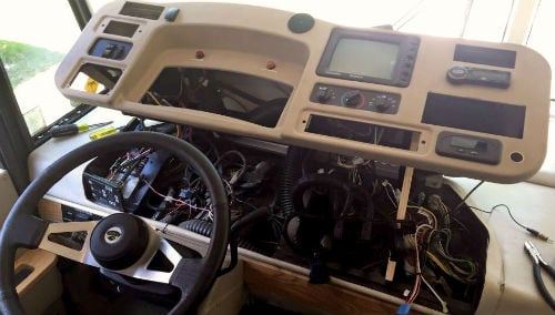 1. Winnebago made a great dash cluster assembly for several model years where the cluster pod swings up on a piano hinge. This allows direct access to every component under the dash and in the cluster. The Actia IP on the other hand is deeply seated behind the cluster fascia and a few screws, nuts and other components need to be dislodged or removed to gain access to the cluster. The use of a hand fabricated prop rod can be used to hold the pod in a raised position for the entire operation.
2. The Actia IP is mounted with five screws around the frame of the bezel. On our Adventurer, the IP is mounted in steel and you need to move the plastic dash face just enough to access the screws. Once the screws are out, the IP drops down and the two modular connectors are detached. The IP can then be easily removed. (Note: You may want to jump right into the upgrade project – but take it from us – follow the instructions. There several procedures provided in the manual and if followed to the “T”, all will go well. What is involved is the disassembly of the IP right down to the system board.
3. The most difficult task was removing the Tach and Speedo needles. The Temp and Fuel were easier to remove. It is recommended that you note the needle positions as it becomes more important when restoring the needles on their posts. Use caution, however, don`t lose the Set and Mode posts, they become loose when the trim is removed.
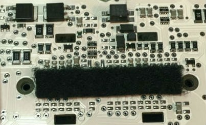 4. The most time intensive task was clipping down the modular connector pins. There are approximately 40 pins that need to be trimmed down. I cut all the pins one way, spun the board, and recut going in the opposite direction. I used a magnifying glass to inspect the results. Once this was complete, I used a soft tooth brush to make sure no traces of copper were left behind. I then used a can of Dustoff to finish.
 5. The importance of trimming the pins is to prevent penetrating the new LCD ribbon cable. A Velcro pad is applied over the cut pins to complete the job and isolate the ribbon cable from the pins. In the new LCD Upgrade Kit, company representative Jon Brazel explained that a small pair of cutters is included to make this task easier and more effective.
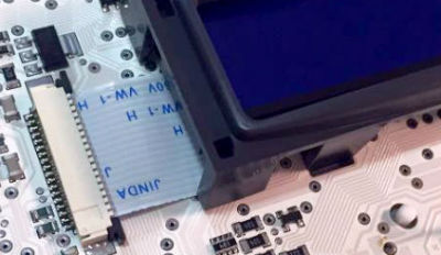
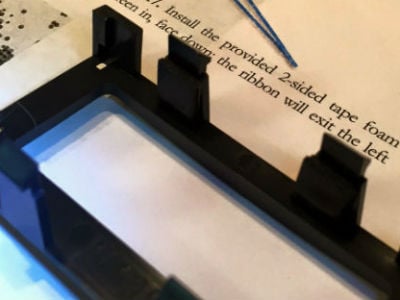 6. The next step in the process that was involved in the installation of the LCD kit was the trimming of the stock rectangular plastic LCD mounting bracket where indicated to allow the LCD to fit. Two pieces of sticky pad take the place of cut-out mounting clips. Use caution where indicated and don`t to get brutal with the edge connectors, ribbon cable and connector on the motherboard. Once the new LCD is installed in its mounting bracket, simply snap it back in place and the rest of the cluster is assembled in reverse order.
7. Be mindful with the Mode and Set posts as they could easily fall out of the face of the cluster while running the diagnostics. After the needles are set, we used eye glass cleaner and a microfiber cloth to wipe down the face of the panel and a few short blasts of air duster to dislodge any remaining fuzz. At this point, pop the face trim back in place, clean the inside of the lens, and restore the front lens to the IP. (Note: Be sure to determine the accuracy of the needles once they are assembled. If the needles are slightly off, use the cluster diagnostics to check the operation and they can be manually adjusted.)
 8. With the IP fully functioning and calibrated, it was time to put the project to bed. The disassembly of the Instrument pod basically went from right to left. The reassembly went from left to right.
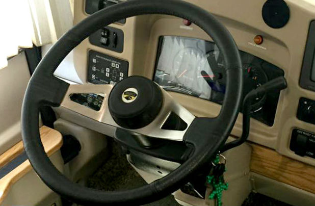
At this point, we were ready to check if the cluster would come to life and after we put the key into the lock cylinder, it did. Once we saw that blue LCD light up, we were on the home stretch.
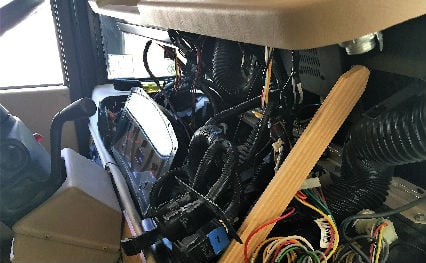
9. Although the gauge pod appears intimidating, only 16 fasteners were removed to dismount the Actia IP. What holds the fascia in place are the fog lamp plate(2), HWH controller(4), center rocker switch plate(4), the radio (removed using a dismount tool), one screw in the top right corner of the dash(1) and the cluster itself(5). To access the top right screw, remove the right side AC register and disconnect the air duct.
 10. I recommend when you’re restoring the fasteners to partially thread them all before tightening since the fascia will move over the metal frame underneath. The radio was inserted last. All the rocker switches are carefully inserted in their respective locations. Pull the AC ducts slightly past the fascia, restore the register and push the duct and register back into their positions before you lower the dash pod. Start the engine up and operate all the switches.
In conclusion, when driving the motorhome under all types of lighting conditions, the data on the command center is clear and immediately discernable without the traditional squint that was a normal practice in the past. The new white on blue background is one of the most efficient upgrades that I have done on my rig as it’s one of the first things you look at when you scan the dashboard during travel.
Nice idea, but lets go back to step one, How do you get the dash assembly to unscrew and swing up? I’ve seen about 4 or 5 different descriptions of getting a Winnie dash up, and all of them are different.
Hi Jim,
Thanks for your comment. There is actually nothing but gravity that holds the dash of the 2003 Winnebago Adventurer and other model years. In later model years the dash pod was secured to the dash itself and didn’t swing up. Removing the IP however would have been similar but perhaps a bit more task intensive.
WHEN YOU SAY LATER MODELS YEARS FOR THE DASH SWING UP ??. I HAVE 2005 ADVENTURER WILL IT SWING UP ??.
How about the 2004 Monaco Monarch dash?
How do you set the gauge needles on a 2004 Holiday Rambler
What is the park position? Thanks for help
How do you calibrate the RPM, MPH Fuel Gauge and Temp Gauge installation are not clear at all?
I have a 2003 Dolphin workhorse and the gauges will click off and sound the buzzer for a couple of seconds then come back on. Will this upgrade solve this issue?
You may unit to check with the company on those problem as that’s not reason I did the upgrade
I have a 2005 southwind rv, with work a chassis,, how do I get the cluster out of the dash, & where can I buy a new cluster, thank you for your answer
did anyone respnd to you? I have a 2005 Southwind also. please respond…