For RVers who travel around to visit friends, it’s great to get together. When you can stay on their property, it’s even better—just pop out the door for a quick visit or barbecue. Still, for the visitor there’s a bit of uneasiness, maybe thoughts of “taking advantage of friendship,” or “not paying my way.” Here’s a project that can help you see to it you care for some of your keep: a portable electric meter that tells you just how many precious kilowatt hours you’ve used so you can offer to help pay your host’s electric bill.
The project is straightforward, and should set you back less than $80—if you know where to look for parts. And we’ll help you with that too!
The project involves working with electricity, which can be dangerous. So if you are uncertain of your skills in working with electricity, seek professional help or don’t do this project.
Heart and Soul: The Electric Meter
Nearly every home in America has an electric meter; there are millions floating around. Sure enough, from time to time electric companies upgrade to new models, or some just need repair. Where do you suppose they go? One place is to a company in Florida whose business it is to test, repair and sell electric meters. Hialeah Meter Company (www.hialeahmeter.com) sold us a meter and meter base (socket) and shipped it to us for less than $50. A trip to a local hardware store gave us the rest of the needed parts for about $30. Had we gone to a big box store, we could have cut the cost on the latter even farther. (See the sidebar for a parts list.)
Our project is designed for a 30-amp RV. Upsizing the system won’t cost a great deal more for a 50-amp rig. But some wonder: A 30-amp RV uses a single “hot” and “neutral” wire, running at 120 volts. Do you have to buy a special electric meter for 120 volts? Nope, we’ll show you how to wire a 220-volt electric meter to work on a 120-volt circuit.
Step by Step
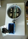
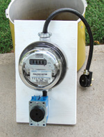
Our portable meter is built on a small but stout piece of plywood. This supports the meter and other components, and can easily be screwed onto an electric pole, fence post or other handy upright structure near the electric supply. We used a chunk of 3/4-inch plywood, cut to about 9 inches by 15 inches, sanded, and painted with exterior paint to keep it from weathering.
Now a little nomenclature: The wires in the system are “hot” (here always black in color), “neutral” (always white), and “ground” (always green). Power flows into the portable meter through a 30-amp “trailer plug” and out to your RV through the 30-amp “trailer receptacle.” The meter plugs into a “meter base” that contains electrical contacts called terminals. The side of the meter where electricity flows in from is the “line side,” and the side of the meter where it flows out to your RV is the “load side.” For simplicity, we’ll call the wiring you’ll use “hookup wire.”
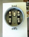 Step 1: Screw a clamp connector onto the meter base, one each at top and bottom. We used Teflon pipe tape to make the connectors go in easier, and to allow us to turn the connectors so that their set screws faced up from the board.
Step 2: Using short wood screws, screw the meter base to the plywood board. We mounted our base so that the top of the upper clamp connector was about 2 inches below the top of the board. Our base had two mounting holes for screws.
 Step 3: Route the hookup wire through the bottom base clamp connector. Strip back the outer sheath of the wiring, and expose enough of the internal conductors so that the hot or black wire can be routed to the upper right meter base terminal. Strip back the insulation, install the wire, and tighten the screw firmly. Leave the ground (green) and neutral (white) wires free in the meter base for the moment.
Step 4: Feed the other end of the hookup wire into the top of the electrical junction box, and out through the front. Allow 4 inches or so for hooking up to the 30-amp trailer receptacle and cut the rest of the length off.
Step 5: Push the wires in the junction box aside and using short wood screws, screw the junction box down onto the plywood, roughly at a center point of the board, just below the meter base.
Step 6: Strip back the sheath from the hookup wire coming out of the junction box. Strip each conductor to the length indicated by the trailer receptacle and connect each wire to its appropriate terminal. Typically this means the black wire to the gold terminal, white to silver, and green to green.
Step 7: Fold the lead wires back into the junction box and screw the receptacle into the box. Make sure that the ground pin—the round one—is at the top of the box.
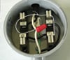
Step 8: Turning to the remaining piece of hookup wire: Measure the distance between the lower left and lower right meter base terminals. You’ll need to cut off a piece of black wire and strip back the insulation on each end to mate these two terminals together electrically. Be sure to tighten the screw terminals firmly. You could use another piece of insulated wire to jump these two terminals together, but the wire MUST be of the same gauge as the wires feeding the other terminals in the meter base.
Step 9: The remaining piece of hookup wire will serve as the wiring for the line side of the project. Feed one end of it through the top clamp connector into the meter base. In the meter base is a ground screw. On our meter base, the ground screw was at about the center of the base, and after removing the screw, a small piece of rounded metal could be lifted up off the base. Cut and strip back the ground wires from both the line and load side so that their bare wiring can be laid under the ground clip and the screw replaced and tightened down. Both ground wires are now electrically connected.
 Step 10: Cut both neutral wires (from load and line side) so that they can meet approximately at the center of the meter base and be stripped back and put together with a wire nut. Don’t cut yourself too short! Before you put the wire nut on, you’ll need to strip back about 3/4-inch of insulation from that tiny (18 to 22 gauge) single conductor jumper wire. Tie this wire in with the neutral wires with the wire nut. Cut off the small gauge wire to about 6 inches long and strip back about a 1/2-inch of insulation from the free end.
Step 11: At this point stop and use a multi-meter to verify continuity between the neutral wires and the small jumper wire. Touch one probe to the neutral wire on the line side and the other probe to the free end of the jumper wire. You should show continuity—if not, go back and redo the wire nut connection.
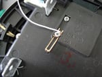 Step 12: Turn to the electric meter. On the backside of the meter you’ll see two small screws with a jumper clip between them. Loosen both screws and open up the jumper clip as far as you can. Form a small loop in the jumper wire (coming from the wire nut connection) and attach the wire to the screw on which the jumper clip remains. Double-check your work here! If you get the jumper wire on the wrong screw you will either trip a breaker or cause a nasty flash! Tighten both screws on the meter base firmly.
Step 13: With the meter board lying on a solid surface with the meter base face up, bring the meter, terminals down, close to the meter base. Carefully align and tuck down the jumper wire so that it stays out of the way of any electrical contacts. Line up the meter prongs with the meter base receiving terminals, meter top “up.” Moosh the meter down firmly to snap the meter into place. Put on the meter lock ring.
Step 14: Strip back the sheath on the hookup wire on the line side and cut back the insulation on each wire to the appropriate length to connect to the RV plug. Again, color code hot to brass, neutral to silver, and ground to green.
Step 15: Test your connections with your multi-meter. Ground side (rounded pin) on the load should correspond only to the rounded pin on the line side. The 7:00 pin position should correspond only to the 5:00 pin position (and vice versa). Any other continuity means going back and checking your wiring. The ground and neutral wires in this installation are isolated from each other and should not show continuity.
Step 16: Tighten both clamp connectors. Goop over openings with weather tight sealant. Also goop the wire passage into the junction box.
 Using Your Portable Electric Meter
If your host has a 30-amp outlet, simply plug your meter directly into the outlet, and your trailer plug into the receptacle on your meter board. If needed, use appropriate electrical adapters to make the transition between your meter board and the host outlet. Remember, if the host system provides 20 amps, don’t “overdo” it by using a larger load.
By doing a meter read on arrival and another on departure, subtracting the “in” reading from “out,” you’ll know how much juice you’ve used on your stay.
Disclaimer: Recognize that working with electricity can be dangerous. If you undertake this project, you do so at your own risk. If you are unsure of your skills, get professional assistance. Neither the authors nor RV Life assume any liability for the outcome of this project.
Russ and Tiña De Maris are authors of RV Boondocking, a book that can make your RV adventures away from civilization more fun and fulfilling. Visit www.icanrv.com for more information.
PARTS LIST
Single-phase watt-hour meter (we prefer the “Easy Read” style)
Four-terminal 100-amp meter socket (base) with 1-inch hub ring at top and bottom
Watt-hour meter locking ring
2 1-inch clamp connectors
1 wire nut (red)
6 feet of two conductor plus ground stranded electrical wire, 10 gauge
30-amp RV plug
30-amp RV receptacle
Single gang electrical junction box (to fit receptacle)
6 1/2-inch wood screws
Weatherproof sealant
Plywood board, 3/4-inch, exterior grade, 9inches x 15 inches
Exterior paint

Can you make it so it can be printed?